It was in 1970 when Dr. Matti Otala (1939 – 2015) read his paper ‘Transient distortion in transistorized audio amplifiers’ at the IEEE proceeding ‘IEEE transactions on audio and electroacustics ‘ (Vol. AU-18, No. 3, September 1970, pp. 234-239). The manuscript is from 1969.
The article was published simultaneously on the Finnish magazine ‘Sähkö’ (vol.44, pp. 7- 11). The article and its claims about TIM distortion led to a worldwide debate, for and against, and later in the Eighties and Nineties – depending on the view – resulted in clear sonic development of transistor amplifiers generally.
A few years later (1973) Jan Lohstroh and Matti Otala presented, based on Otala’s original study, the famous article ‘An audio power amplifier for ultimate requirements’ at the AES 44th convention held in Rotterdam. The paper carefully explained how to avoid the problems that were brought forward in the original TIM-article. At the time, both men worked for the Philips Research Laboratories in Eindhoven.
The 1973 article provided the basis for ‘The 2 Channel Audio Amplifier’ later commercialized by the Norwegian company Electrocompaniet. The 2 Channel Audio amps are much sought after nowadays and have become collectibles. It is kind of unfortunate that the reputation for the design of the amp, which was clearly the result of the two working together, was mainly assigned to Mr. Otala.
For more info on the background of the 2 Channel Audio Amplifier and the related pre-amplifier can be found in this INNER article.
A Finnish amplifier project
Around the time when the 2 Channel Amp was first launched in the late 1970s, I worked, as a novice within a large group of skilled and advanced telephony transmission professionals, at the Telephony Laboratory of the Telecom Finland. Some of us were also audio hobbyists, and in that capacity decided to give a try to a new amplifier project based on the Lohstroh- Otala concept as described in the aforementioned AES paper (including the complete shematic).
Right from the beginning it was evident to us that a proper printed circuit board was required for the project. Fortunately, we had on board a very skilled designer of printed circuit boards, Mr. Oiva Harjunpää. He had an unbelievable intuition to quickly place and track the components by using a black PCB tape between round black PCB taps on an transparent paper in scale 2:1, this being the main method used at that time.
A professional company (Painokytkentä LTD in Helsinki) then made the PCBs according to these taped transparents via 2:1 downscaling photography, on a 1,6 mm glass fibre board with reasonably thick and tightly fit tinned copper tracks (unlike modern PCBs with which even the first component soldering can be a real adventure, PCBs of the past posed no problem to desolder and change a component even five times or so!)
But who would actually build the complete prototype? At that point, eyes turned to me, as I already had acquired quite a bit of practical experience and skill to build transistor amplifiers straight from schematics (without too deep analytical understanding back then, I must admit), my models mainly designs published in DIY-articles on ‘Wireless Word’; absolutely amazing amps by such renowned designers as A.Bailey, J.R: Stuart, H.P. Walker, P. Baxandall, J.L. Linsley Hood, and later E. Borbely.
With an enthusiasm of a novice, I built the prototype. Right a way it worked properly and blamelessly. We were totally amazed by the sound quality of the amp, unheard – so we felt – from an amp with silicon transistors. In my opinion, the only comparable transistor amp at the time was J.L. Linlsley Hood’s ten-watter Class A design with capacitor coupled output, which I had also built up previously.
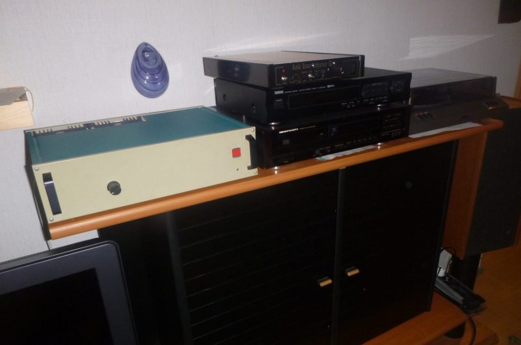
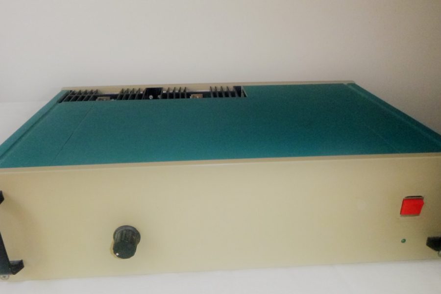
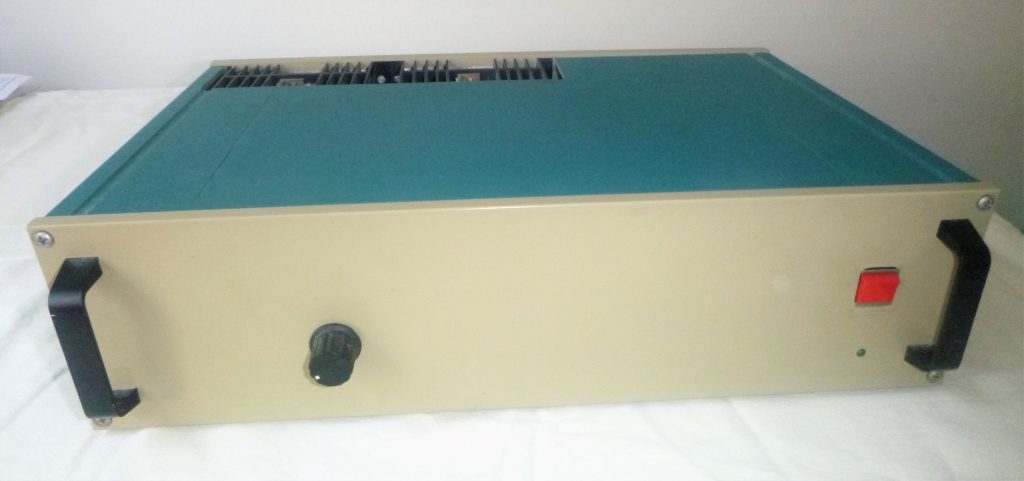
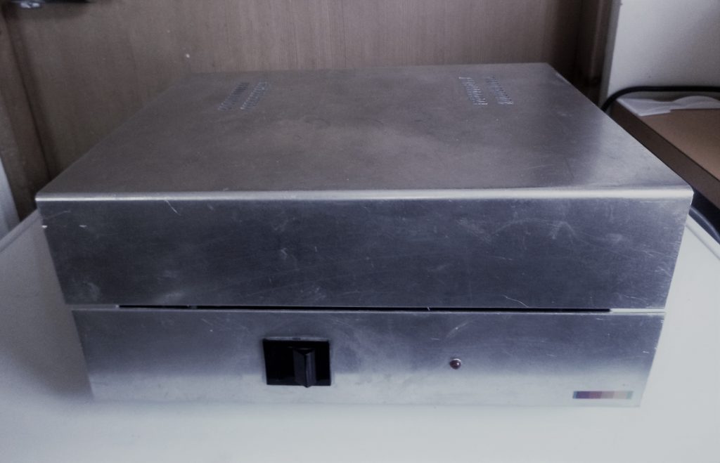
Overall some fifteen units were successfully finished, most of them using the DS9320 telephony modem’s (nicknamed “big”) strong aluminium case shown in Figure 2. Unused cases were available practically free of charge after NOKIA’s decision to discontinue the production of these particular modems. (Just for your info, the speed of the modem was huge 1200 bps, up to the telephony standard V.23.)
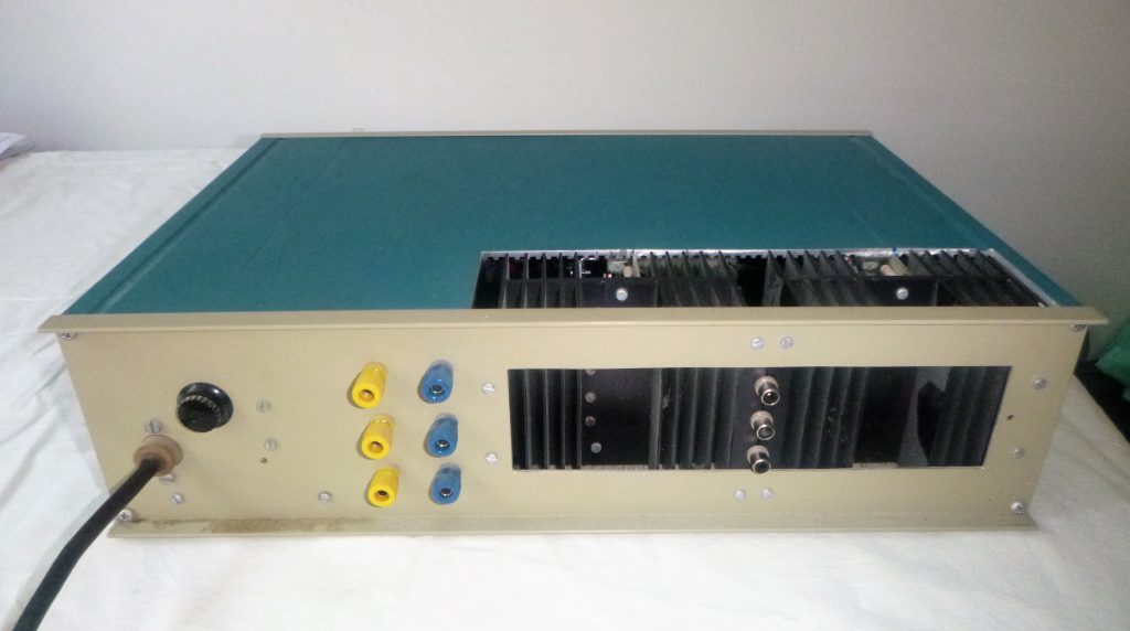
The particular amplifier shown below (installed in a self-made aluminium sheet case for a simpler open construction) was made for a known Hi-Fi enthusiast who had built a 290L bass horn (a Klipsch clone a la instructions published in the ‘Radio &Television’ ). He used the speaker in the Orthoperspekta system (Köykkä OP) as the main (mono) channel speaker, and needed a quality amp to drive the horn system with a passive crossover.
I also helped him by making the 700Hz mid-range horn out of birch plywood meant to be used with the Isophone BPSL100 four inch Alnico driver, while the HF horn was the aluminium Isophone DKT110. In the Köykkä OP system, one channel of my amp drove the horn stack, and the other was used for the S-channel. For the purpose, I also DIY’ed, based on TL074 operational amplifiers, a solid-state stereo pre-amplifier with tone controls, and incorporating an electrical matrix to derive the M/S signals from the L-R difference channels. The pre-amp featured a fine RIAA stage with a NE5533, a new recently released OPA. The RIAA (and later also the stereo line amplifier, but without the M/S matrix) were subject to a number of DIY articles published on the local Hifi Magazine (Hifi-lehti) and is still fully on par with modern OPA designs.
Everlasting piece of gear
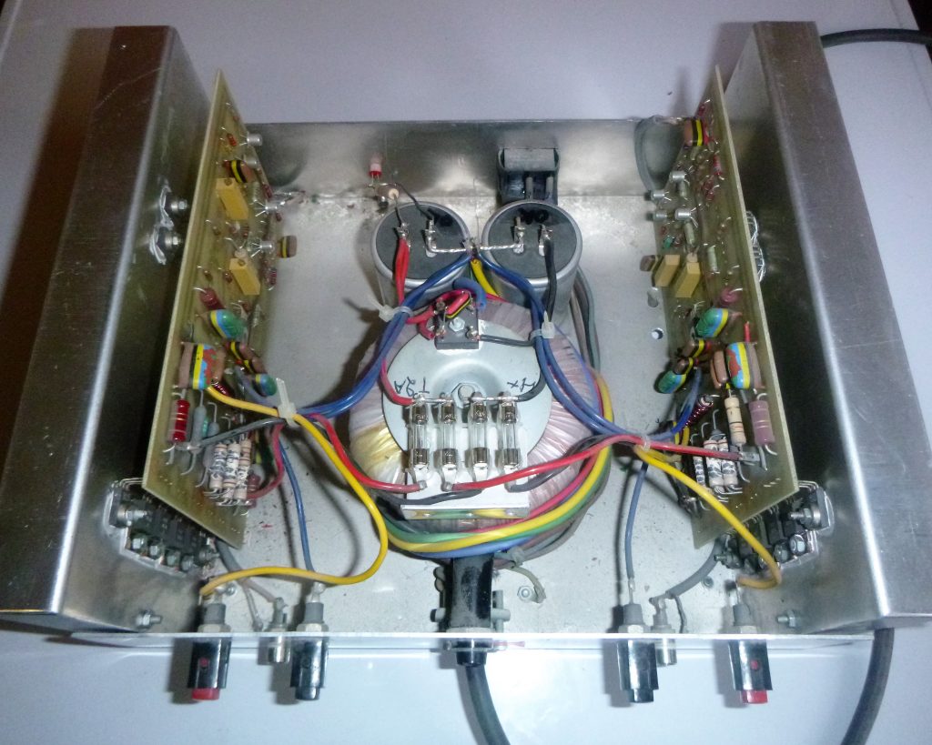
Both Lohstroh–Otala amplifiers described above are still serving well after nearly forty years without a single fault or component failure, one possible reason being that no electrolytic capacitors were used in the amp itself (the only electrolytics were in the power supply mainly using Rifa 4 x 10 000 uf bank of professional types, fed by 2 x 22V/150VA toroidals to get 2 x 30V DC.)
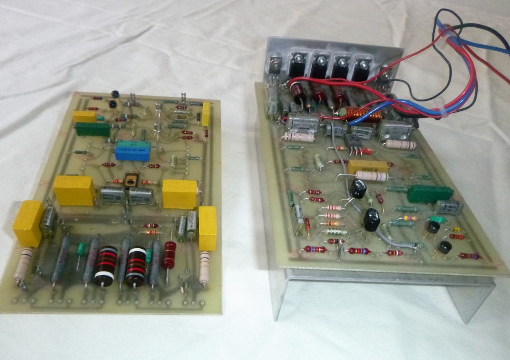
The Figure below shows the printed circuit board. I still intend to build one working unit by making use of these boards.
To cut a long story short, the amplifier circuit topology is a high–power operational amplifier, cleverly used in the inverting mode, which may partly explain the good sound quality. Another explaining factor could be the parallelled end transistors, a topic that was later highlighted by D. Self in his famous articles (‘Wireless World’) on the transistor amplifier design. And thirdly, total lack of signal capacitors in the signal path makes the system free from any cap charge or recovery side effect.
After having experimented with higher supply voltages for the pre-stages, as described in the original schematic, I decided to try connecting the high voltage pre- stage power feed straight parallel to the lower voltage output stage’s power feed (with 2 x 4V lifted DC to maintain the output power) with practically indistinguishable differences in the main output parameters, but with much easier construction (apart from some potential hum problem, which I didn’t come across). The main reason for the original voltage arrangement was that the end transistors would always cut off first on overloads. I also lowered the prototype’s standing current from 500 to 300mA (to 150 mA in the version with smaller heatsinks) without noticeable changes in measured distortion.
For the purpose of this article, I re-checked the output DC voltages, and they had shifted from zero only by 40 and 70 mV, and the standing currents were exactly as I adjusted them forty years ago! Lohstroh and Otala had solved the DC drift problem in a bright manner by using a couple of Philips dual transistors BCY87/89 in the front end of the topology. These transistors were a bit tricky to reach as they were ment for professional equipment only and were not sold at component shops. (I also experimented with connecting two separate plastic transistors together with silicon grease within a shrink tube and this was usable, but the drifting offset in the output was in the order of +- 80 mV; see the Figure of the printed circuit boards).
It won’t be necessary to present the exact and complete measurement data here. The main parameters (and much more) of common interest are given in the original ASS paper and are still valid. With the simple power feed arrangement that I used, the prototype gives 50W to 4 ohms and 34W to 8 ohms with 2 x 30V DC voltage feed. Distortion with 10W /I kHz into 8 ohms is 0,07% (measured with my HP 8903B distortion analyzer). The 50 kHz square-wave is faultless. The only solid state amp from my collection that can compete with this amplifier, in terms of measurements, but also in view of sound quality, is Hafler DH200 – Erno Borbely’s famous robust Hitachi complementary mosfet 100W design. However, its sound signature is slightly different and idiomatic.
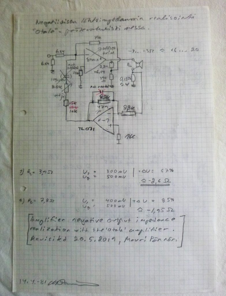
Years later I put the amplifier in service in order to test my subwoofers, since it was easy to fix the negative output impedance around the inverting topology. This can readily be seen from the paper I happened to find from my archives. I lent the idea for personal use from Karl-Erik Ståhl’s papers on patented ACE-bass principles published in a Swedish Hifi- magazine ‘Radio & Television’. Now it was made easy to experiment with different 8…10 inch subwoofer drivers in enclosures smaller than the “normal” size, by adjusting the negative output impedance in the area -1…-3 ohm. It only required turning the trimmer around the TL071 feedback inverter. Back then, the KEF B139 was one of my favorite woofers with a long throw and smallish Vas. The subwoofer box is still kicking strong and the response descending down to 30Hz or so (nothing special today).
Listening comparisons with friends, other hobbyists and colleagues have always produced the same conclusion: This old topology is still highly competitive, and performs strong, even if compared to the sound of any of today’s transistorized amps and as such is a solid bench mark in audio design.
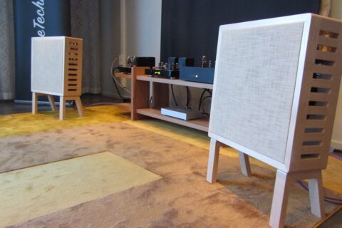
Below: the amplifier is still going strong after forty years!