After the Second World War, and even before, Europe and America were rich with radio receiver industry, smaller or bigger scale, also here in Finland. The smaller Finnish factories begun to vanish towards the end of the fifties one by one, and when FM radio transmission took off in Finland in the mid fifties, the remaining bigger factories, ASA, Salora, Fenno, Helvar and Helkama all had fine tube-based radios in their production line for home FM radio reception. By the end of the sixties these receivers had been replaced by transistorized (also stereo) models, and a bit later by proper home Hi-Fi, ASA and Salora being the last surviving Finnish manufacturers expanding their production to portable and car radios, and also from black and white TV to color TV receivers.
While having owned and restored some of those old fine tube radios over the years, every now and then I’ve come across models with an unexceptionally nice radio sound. Typically the tube selection of these receivers is quite similar to each other, from antenna input to audio detection, and the audio SE output tube most often being EL84 driven by EABC80, a combo that practically replaced the earlier smaller power EL90, for some 3…4W pentode SE power.
A fine-sounding radio worth making acquaintance is the Finnish Fenno model Tähti F324V (Fenno was a Philips owned Finnish factory in the 60s). And lo and behold, inside there is no EL84s but two ECL82s at the audio output stage utilizing an unusual parallel topology (patent pending but never admitted). Another nice sounding unit was Salora Futura, the factory’s last small tube radio model from the mid sixties, with one ECL86 for audio amplification and power of a couple of watts. These two tubes of the fifties/sixties – ECL82 and ECL86 – are quite similar in many respects, and originally meant for black and white televisions but have since got footstep and respect among audio amplifier DIYers as well as found their way to some commercial Hi-Fi tube amplifiers.
LET’S GET STARTED
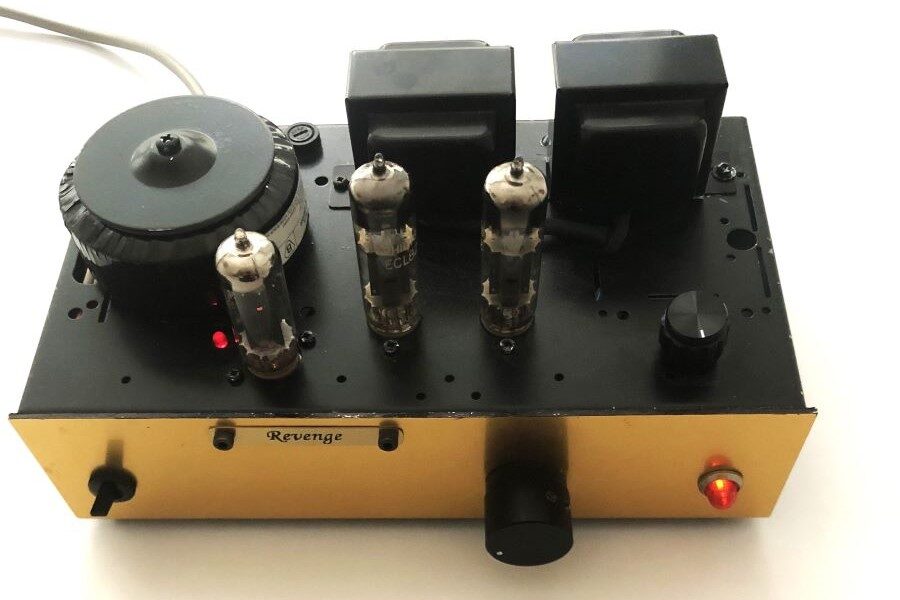
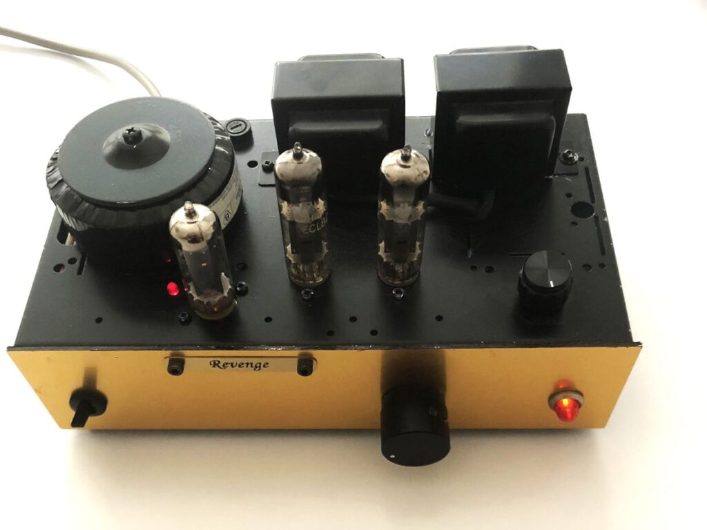
Some time ago I flicked through an old book on my bookshelf: “Mullard – Tube circuits for audio amplifiers”, reprinted in 1993 and originally published in 1959. An there it was, as I fuzzily remembered: a three-watt stereophonic amplifier design with two ECL82 tubes at the output, and a EZ80 as a rectifier. Nothing more urgent under way, I decided to carry out a quick and dirty type of experiment with the schematic, having nearly all the necessary components at hand. As it happened, the construction of the amp wasn’t so quick but the end result was not a dirty but clean sounding amp!
In this kind of pentode output topology the primary impedance of the output transformer for the tube selected is utmost important, and also anode voltage dependable, in addition to the overall iron quality, of course. The trafos in my stock were either too big or too expensive to be used here, but fortunately the Finnish tube component seller Uraltone Ltd had just taken a new 5 kohm/8 ohm /5W smallish Hi-Fi output transformer onto their list. So I decided to try them, also in order to provide proper feedback to Uraltone, as I have done before in various cases of co-operation. The construction itself was then straightforward given my over 50 years of experience and relevant skills.
A BIT MORE OF THE EXPERIMENT
I took one busy weekend in my countryside workshop to assemble the amp. Everything worked fine right from the beginning. Originally the overall negative feedback from the output transformer secondary to the input stage’s cathode was circa 6 dB (quite low to get reasonable input sensitivity, Mullard’s original note) but I chose a bit higher value, 12 dB. The transformer worked as promised giving the bandwidth from 30Hz (14H primary inductance ) to 20kHz (-1dB), and 30kHz (-3dB). The output power was 1,3 W with 1,5% distortion, those figure being in par with the old Mullard measurements. The transformer also showed only a modest iron distortion at 40Hz/1,5W, which is an acceptable figure for the trafo of this size. The sound was surprisingly good. The amp kicked my old KEF Concertos to sufficiently enjoyable levels in my city living room.
However, the additional goal of the project was to experiment with various feedback tricks, and their combination, within the SE pentode topology, and also to study the effect of different screen grid voltage feed arrangements. Firstly I removed the overall feedback and added feedback locally to the output tube by moving the output transformer’s 8 ohms secondary to the pentode’s cathode in a proper phase. The original overall feedback from the secondary could not now be used due to the necessary phase reversal in the transformer with two amplifying stages only. I have made use of this trick in many of my own designs, and with success. It sounded OK, but distortion figures were not essentially better compared to the original, as only 5dB of feedback could be obtained here (depends on the pentode’s amplification factor and output transformer’s winding ratio). Next, I decided to try the so called RH feedback idea on which I had read on the net (goes back to old RCA amplifier topologies and tricks). I took about 3 dB of feedback from the output tube’s anode, via a biggish resistor, to the driver triode’s anode. But my HP audio analyzer still showed 1,5% distortion at 1W, meaning that there was no need to continue as there were no further possibilities to do this remarkably better with the available components and topology. (It should be noted that the RH anode to anode feedback cannot extend the bandwidth upwards or downwards, determined now by the output transformer properties, assisted by the local cathode feedback from the output tube.)
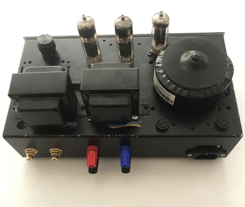
The construction utilizes diode supported Graetz-type anode voltage tube (EZ80) rectification (no midtap is needed in the anode winding) and a simple CRC anode filtering. The screen grids go straightly to the anode voltage feed via 1,5 kOhm resistors. I tried also 20V zener drop diodes here with no further improvement, and went back to the original resistor feed. A 150V (OA2/150C2) gas tube stabilization could be an option. I tried a new grounding solution: a PCB copper plane serves as the ground plane, insulated from the chassis and grounded only to the power supply/chassis common ground point. All electrical grounding of components is done randomly to this plane with good results.

CONCLUDING REMARKS
I have used this unit now for several months and am still enjoying it, no sign of listening fatigue whatsoever. It keeps amazing me how this 65 years old holy simplicity offers a very enjoyable musical reproduction. This amp will not leave my otherwise constantly changing amplifier repertoire (some 20 individuals of my own design). The reputation of these old TV tubes, and the way they sound, is justified. I’ve built numerous triode and pentode SE amplifiers throughout the years, and would claim, that the sound of these amps do vary, and the differences sometimes easily recognizable. Without going deeper into the reasons of why, I’d say that good designs, triode or pentode, are both able to offer fine listening moments. And now, more music on the platter!