Having had the pleasure of knowing Mr Köykkä (1911-1994) personally already in the 1970s, and being now, 40 years later, aware of all of his achievements in the field of audio engineering, I would rank him, even though he’s less well known outside the borders of Finland, to be on par with such past audio designers as D. Williamson, H. Leak, F. McIntosh, D. Hafler, S. Maranz, P. Baxandall and P. Walker. And in this article I’m especially thinking of his career via my 6BX7 PP amplifier.
At the end of this article I will make an attempt to argue for my understandably bold proposal. Until then, in what follows I try to be as objective and realistic in my judgment as possible. To the extent possible, I’ve corrected all uncertainties, and checked all possible facts, and will stick to them only. This all despite the fact that I’ve got huge respect for Mr Köykkä’s work ever since I visited several times his workshop back in the 1970s.
Inspiration from an old amplifier design
A majority of the text below was written more than seventeen years ago, when my own triode amplifier prototype (explained in detail below) had shown its sonical potential in daily use over ten years, pushing my small Fostex loudspeakers into pleasant spheres in our living room. At the time, there were only occasional weak signals of a will to bring Mr Köykkä’s findings into broader daylight, and subject them to further study. Today the situation is entirely different. In the course of past few years, a number of skillful Finnish tube amp hobbyists have made a great effort in reviving Mr Köykkä’s work.
So I do realize that I’m a bit late with this article. The impetus to publish the text now came from my taking my old amplifier construction on a table and using it after a longish period of time; in addition: all the patens mentioned in the text are no more valid.
Also, I begun to wonder, if I’ve been able to reach any sonical progress with my over ten tube amplifier designs in the course of past twenty years or so (most of the designs have been published as DIY projects in different magazines). The answer to this question is: Yes, there’s certainly been progress, but not as radical as one would guess. Nevertheless, it’s certainly been a highly rewarding and adventurous research period. My sincere hope is that I’ve been able to develop and deliver, by means of all the articles, so called “quiet knowledge” for the benefit of younger tube amp enthusiasts.
Back to the roots: From Single Ended Push Pulls to Voima OP3 PP
I’ve been a HiFi hobbyist about 50 years, of which some 30 years I’ve been focusing mainly on tube amplifiers. Every now and then I’ve come across exceptionally interesting tube amp designs. One such amp is based on an old, no more valid Finnish patent nr 33483 from 1964, held by the aforementioned Mr. Köykkä.
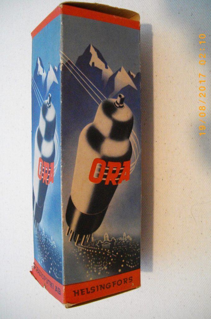
Mr. Köykkä had made a long career in audio engineering before reaching the patent for this amp. Among other things, he had a major role in raising the Finnish tube radio receiver manufacturing to the high level it was after the WW II. He was also actively engaged in establishing the Finnish radio tube factory project in the 1940s (the tube brand name was ORA, see the pic below). However, the production didn’t last too many years under the heavy all-European competition. Nothing new under the sun.
More importantly, Mr. Köykkä was one (though not the only one as many still seem to believe) of the main inventor of the world-famous single-ended push pull bridge amplifier (SEPP) concept, still appreciated as one of the best and cleverest tube output configurations by many.
Regarding the SEPP, he held two Finnish patents from 1955 (pending from 1952) and 1958 (update, pending from 1955). Unfortunately, he didn’t have the sort of money (or maybe serious will?) that would have been needed to take further advantage of his patent. The idea of the of the SEPP was simultaneously in the air in Europe and in the USA. Electro-Voice/Wiggins Circlotron was perhaps the best known commercial brand to make use of it. Philips too picked it immediately, for free, for commercial purposes, after having seen Köykkä’s introductory article in an European magazine ‘Funktechnik’, 7/1953, as Köykkä himself later told us.
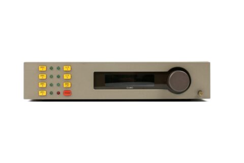
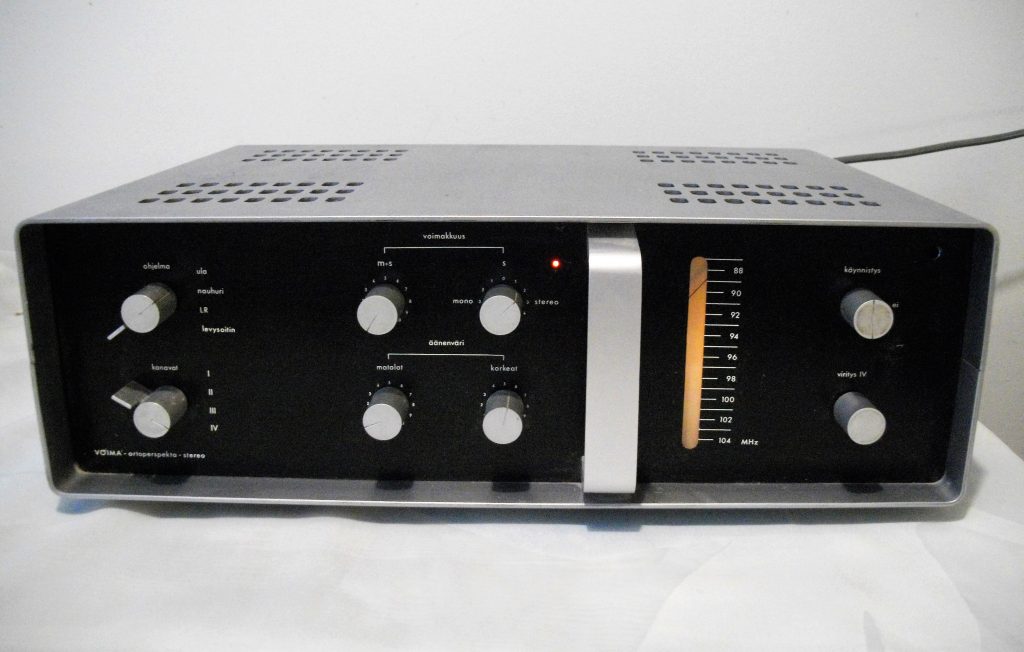
All this is well documented and info readily available on the internet nowadays. In Finland, Mr. Köykkä designed, based on his SEPP-concept, a mid-fi/medium scale commercial amplifier/a FM tuner, sold under the brand VOIMA (’POWER’ in English). The amp was primarily meant for broadcasting purposes and PA systems, but also for HiFi enthusiasts. The VOIMA amps were selling quite well, and are now much desired items, and highly ranked restoration objects among local tube hobbyists. I personally own a couple of different models, one based on Köykkä’s later (1964) amplifier topology with another Finnish patent, including his other invention in music reproduction called ”perspective stereo” or ”Orthoperspecta”, for which he also had a patent.
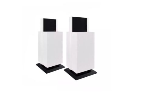
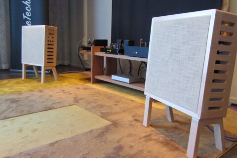
The patented VOIMA OP3 Orthoperspecta concept, and amplifier/receiver mentioned (see the pic above) consists of a summed (L+R) main front (center) mono M-channel amplifier providing some fifteen watts music from 2 x EL84, and two small opposite phase (as push-pull) S-channels (L-R, R-L) to be reproduced by means of two rear loudspeakers at the opposite side walls, fed by one EL84 with a restricted bandwidth (300Hz…3kHz).
L/R stereo to M/S matrixing is cleverly executed electrically at the preamp stage. The summed main (mono) front channel has a definite one-point reproduction, where the rumble of LPs and the record player is practically cancelled out. The perspective of the sound in the room is continuously variable with the separate S-channel volume control. All this holds another Finnish patent (1966, nr 35014, pending from 1962).
This spesific amplifier, VOIMA OP-3, rare as it is, has been a true collector item in Finland. The designer of the chassis of the amp was a Finnish architect Yrjö Turkka. According to a legend, the amp was on display at the Milano Triennale’s design exhibition around 1971. However, I have not been able to verify the information.
Unfortunately, there is no more substantial interest in the M/S reproduction concept – for an uderstandable reason, I’d say – among younger hobbyists. However, there seems to be a new wave for mono HiFi home vinyl reproduction and here, take my word for it, we have an excellent amplifier (MM RIAA included) for the purpose, including in excess also a fine FM tuner (made by the Danish Larsholt). No need to dwell on this issue longer; suffice it to say that the idea of M+S reproduction is not unique: similar ideas were presented in the 1950s by other amp designers (I’ve seen an old paper proposing a similar system as an inversion to the more commonly used MS recording technique.)
 About tubes
Mr. Köykkä knew his tubes. EL84 and EL34 were his basic tools, and the ever useful ECC81 and ECC85 were his favorite front stage components in the 1950s. For his RIAA-stages he chose EF86 and later ECC808, a post-manufacture version of ECC83, quite a rarity today. There are no essentially better tube components nowadays than back then: the same tube types exist, but the manufacturing quality is typically worse. Luckily hobbyists still can rely on NOS tubes.
Köykkä’s last tube amplifier construction, following mainly the concept presented below, was designed in the end of the 70s. It was based on two PL504 frame tubes, approved now by tube freaks, including a clever automatically gliding bias control from class A to B with about 50 watts output, again with one ECC81 at the front and ECC82 cathode followers driving the power tubes in the style of McIntosh.
I’m not sure whether the amp ever was commercially sold, but Mr Köykkä gave me its schematic around the end of the 70s. (Just for your information, I have recently introduced a cathode follower SE amplifier around the PL504 tube, published in a Finnish net audio magazine.) This amplifier is also able, via a capacitor straight from the cathode and without inductive coupling, to drive my old Philips 800 ohms wide banwidth speakers, namely the AD 5038, also rare but very good sounding indeed.
In this context it is worthwhile to remind that Mr. Köykkä was also the pre-inventor of the transient intermodulation distortion (TIM) in feedback amplifiers at the end of the 60s, as indistutably shown by some articles Mr Köykkä wrote for Finnish audio engineering journals (eg. ERT magazine 1/1969). The TIM theory was then investigated, proved, and sold to the world by the Finnish Dr. M. Otala via AES in the beginning of the 70s, leading to a worldwide debate in respectful audio magazines continuing over years and decades, and occasionally even still.
My own take on the Köykkä’s OP3 amplifier concept
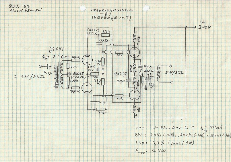
It was the output stage of the VOIMA OP-3 receiver schematic that inspired me thirty years ago to build a normal L/R stereo version, the first one under my own ‘Revenge’ hobby brand name. The hand-written schematic (found it from my archive after thirty years!) is shown the pic above. About the same time I had built quite a sensitive widebandwidth, high-definition speakers around the Fostex F103 Sigma driver, and with them wasn’t any more fully satisfied with the audio quality of my expensive Yamaha CR1010 receiver with its 80W transistor Class B hybrid outputs with very heavy feedback, even though it was an elegant amp in its own right.
I didn’t want to copy the VOIMA amp directly as I had some ideas of how to improve it. Keeping in mind how Mr. Köykkä had spoken for triodes in his above mentioned ERT article (e.g. as vinyl cutter driver tubes) in the 60s, long before the current triode boom, I began to look for suitable 6,3V real triode candidates to substitute the 2 x EL84 pentodes. The idea was to use them with the output transformers I bought from Mr. Köykkä in the early 70s (Mr. Köykkä was always very open-minded and kind towards hobbyists, selling them components and giving them patented schemas for free for private use).
I cannot recall exactly when and wherefrom the 6BX7GT double TV triode came to my way, perhaps the idea originated from a copy of an old US magazine from the 50s. Surely, in those days no one in HiFi circles paid any attention to this TV tube! Anyway, replacing the EL84s and using the same transformers could hardly be easier: just skipping the screen connections, and that’s it.
As said, all this took place thirty years ago when, apart from Jean Hiraga (and his famous book), only very few in Europe showed any interest in SE triode designs, although the topic had already been hot in Japan for years. By the way, maybe the best and most cost effective and ingenious utilization, and drive of EL84s in PP configuration can be found in the splendid Dynaco ST-35 (I’ve got one). Today Luxman and Leben are basically riding on this old and proven concept, with variations.
I did some experiments with conservative tube phase inverters, schmitt and split types, (used e.g. in the Dynaco) but was not fully satisfied with those solutions. I wanted the design be fully symmetrical, and having recently designed telephony carrier ferrite coils and transformers in Telecom Finland’s lab where I worked at the time, I suddenly realized that it was definitely the transformer that I had to try for the phase splitter!
By accident I noticed that some fine surplus stuff from the Finnish Radio Broadcasting Company were on sale at a local HiFi hobby shop, including excellent tube interstage and output transformers made in Denmark, marked JS (=Jörgen Schou). JS manufactured top level studio and audio transformers around the 1950s. The 2,5 kohm/100 kohm JS line transformer (model 689) was suitable for the purpose giving some 45 kHz bandwidth with free center-tapped gain of about six!
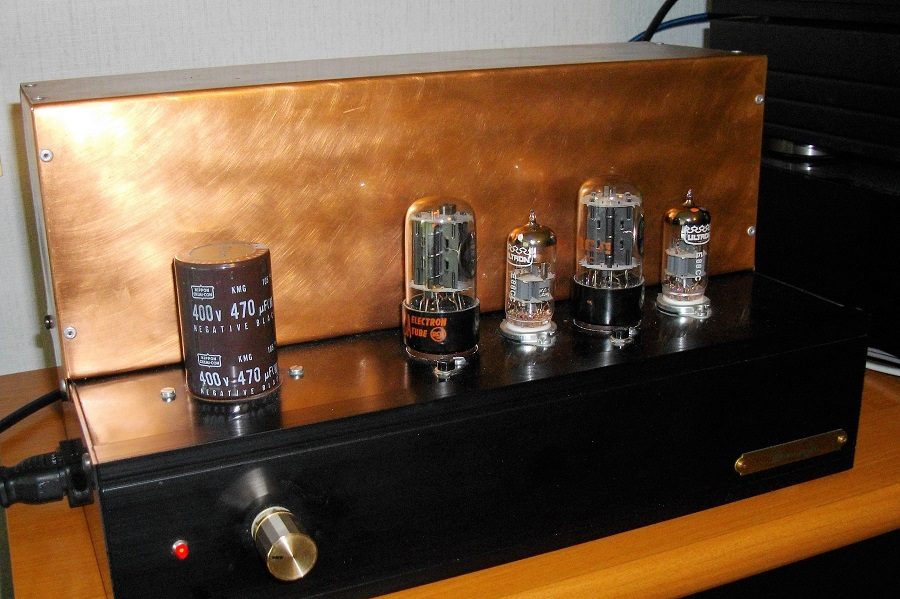
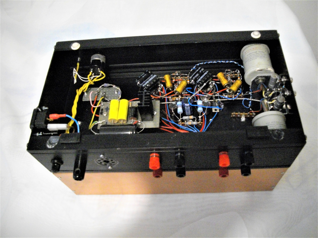
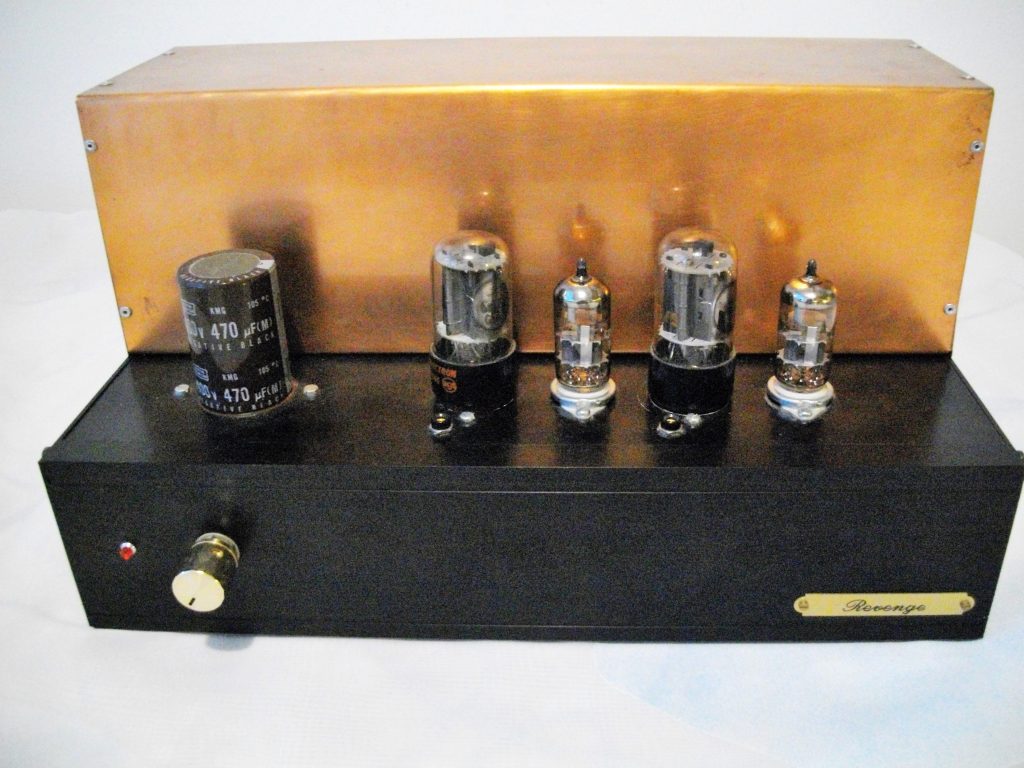
As to the driver tube, my original choice was the high u/low Ri ECC85 in order to have maximum differential gain. It was Mr. Köykkä’s favourite tube. The power transformer was an ugly individual from the same surplus BC stuff giving about 2 x 270V /150 mA, and 2 x 6,3V/2A/. I hid all the irons underneath a self-made copper cover (see the pictures).
First impressions
One weekend, when my prototype was finely ready for playback, I chose classic music from my FM tuner (it was about two o’clock in the morning), and begun to listen. The result? I was utterly shocked about the sound quality! I hadn’t heard such a quality sound before, young as I still was. The sound quality moved me up to tears. That has happened to me only very few times in this hobby. My DC-coupled Revenge E182CC SE (published in AudioXpress, July 2003) was another similar case I can clearly recall, and my Revenge RIAA five years back perhaps too (now available as a construction kit or a readily made product via Uraltone Ltd, Finland).
The u-metal shielded JS input transformer/phase splitter works here backwards with a voltage ratio of about 1: (3+3) giving free gain without noise, thus actually also partly replacing one low-u pre-driver tube (e.g. ECC82 or 12BH7). It is terminated as center-tapped to 2 x 100 kohm reflecting some five kOhms to the input. This is quite a low value, and puts pressure on the preamp output impedance to ensure sufficient low frequency output (my Revox A77 reel deck’s front end, via direct out, was an exellent pre-amp for test purposes at my test bench back then).
The anode resistors of the driver tube have dynamically extended supply drive (”bootstrap”) from the output transformer anodes to add positive driving voltage capability, because the required output tube grid swing is in the same order of magnitude than the swing at the 1:1 output transformer’s anodes and cathodes, around 90V rms. The topology can be seen in my original schematic thirty years back, in picture 5. The same trick, not very elegant to my taste, was also in use in Köykkä’s small-wattage SEPP amplifier models. For easy biasing, my differential driver stage had originally a low value (600 ohms) tail resistor for three milliamperes through each tube halve, working satisfactorily. A later experiment with a 6 mA FET constant current generator from the cathode to a negative 8V supply, derived from the heater, works also well bettering the unbalance between the triode halves.
The core of Köykkä’s patent
Here, as stated earlier, the output tubes work with 1:1 anode to cathode signal voltage in a split-type transformer winding solution, and necessitating the hard driving swing requirement. It’s not a news in the transformer world that a tight coupling between windings in always needed in order to eliminate the leakage inductance effect. The concept is familiar from the McIntosh amplifiers, which have 1:1 bifiliarly or even trifiliarly wound anode/cathode/screen CT windings. According to the Audio Bible ‘Audio Cyclopedia’ McIntosh also interleaved the primary and the secondary to five sections; this I have been able to verify from certain documents later.
And now, the core of Mr Köykkä’s patent is this: one can use a very simply and cheaply made output transformer for exellent results by connecting the same-phase ends of the transformer 1:1 CT windings with smallish capacitors, thus shunting the leakage inductance between the windings at higher frequencies.
The original VOIMA output transformer (see the pics) for 2 x EL84 has a 3500 ohms CT winding near the EI core, then a 0- 4- 8 ohm secondary winding, over it another 3500 ohms CT winding and finally an 8 ohm secondary, all without any sections and with noticeable resistance differences between the four primary halves.
At any rate, the main windings in parallel, these transformers measured (in my test bench) quite a modest upper bandwidth, 13Hz (-1dB)/15kHz (-1dB)/38kHz (-3dB), but in this amplifier concept, they sounded excellent! Comparable McIntosh amplifier models go, with their overall feedback, typically near 100kHz (-1dB), impossible with the components I used here, the JS transformers included.
All that is said above must be reflected against Mr. Köykkä’s firm opinion, that 20 kHz, and this definitely without overall feedback and modest THD allowed, is sufficient for the performance of HiFi amplifiers. We may or may not agree. My measurements reveal that the claim of transformer simplicity may not be so valid against today’s requirements, and that the ideal solution now would be a sectionally better constructed and balanced unit with some 60 … 70kHz bandwidth using the patented capacitor trick only in assistance. Or alternatively, use the expensive bifiliar solution. Nothing prevents from trying the trick in a McIntosh amp, but I bet it gives not much there. Today I am sure any respected OPT manufacturer, e.g. Sowter, is capable of producing a suitable unit for individual needs.
Nothing new under the sun
Later on I noticed that the capacitor trick had been introduced in an old (reprinted) GEC tube amplifier handbook, December 1957, in connection with a 1:1 push-pull Class B grid driver transformers. So it seems that the idea wasn’t originally Mr. Köykkä’s invention as patented in Finland in 1964. Also, an even earlier transformer text straight from a McIntosh Engineering laboratory’s article in the US ‘Audio Engineering’ magazine, December, 1949, states:
“It is obvious that other variations (than bifiliar winding, editors addition) of approach have been considered which accomplish the desired purpose to some extent at least, such as winding the two primaries on a common core not bifilarly and utilizing a suitable capacitance for coupling the ends of these windings so as to maintain the two windings at proper and identical a.c. potentials”.
So why did Mr. Köykkä try a patent over ten years later, and why was the patent approved? It is even more strange knowing that in his patent application Mr Köykkä openly mentiones the McIntosh article accurately as a source, which I consider as very honest and honorable referencing practice. Clearly the approving committee (Finnish Patent and Registration Office) has either been negligent or simply lazy about checking the facts.
The same trick is often cited in old telephony engineering literature (to be found eg. in the Telecom Finland’s huge library). With 1:1 wide-bandwidth telephony transformers, iron or ferrite, one can get an increase approximately of the size of half an octave in the upper frequency band by using the capacitor shunt. Respectively, it is possible to obtain the same amount extension at the lower frequency end by adding a suitable (tuned) capacitor in series to the transformer primary. This works properly only in constant impedance solutions, as was typically the case in carrier telephony.
Unfortunately, there is no free lunch. The solution results in an increased phase shift at both frequency extremes, appearing as an excessive sag in the square wave test at low frequencies. That does not look neat in an audio scope, but in carrier telephony it had no meaning. Generally speaking, it is quite difficult to design a transformer covering much over four decades of the bandwidth, without one or both of the mentioned tricks at the extremes, or without very complicated winding techniques.
 My own results with the power triodes
The power stage concept described above turns the main part of the inherent voltage gain of the output tubes to local feedback, giving here acceptable, if not very good THD (0,3%/1W/1kHz). Nothing exceptional though: my Revenge EL34 triode PP fully symmetrical design, now with a Sowter 3575 splitter 1:1 CT transformer at front, gives an order of magnitude lower figures in a “normal” PP topology, and the same amount of BW without any feedback.
I’ve used the trick successfully also in SE amplifiers with high-u power triodes (e.g. F2a in triode mode) putting the output (loudspeaker) winding at the cathode, giving 3…7 db of feedback depending on the triode and transformer winding ratio (ref: my article ’The DC revenge E182CC amplifier’ in AudioXpress, July 2003). The famous Quad II amp is also a fine example of a PP design in which the trick is made use of, with a modest turns ratio.
I did comparisons between Class A and Class AB: no worsening in distortion figures worth mentioning between the two. The power supply consists of 4 x 1N4007 diodes in a bridge and a 470uF capacitor straight after, giving over 300V DC. Nothing else is needed, thanks to the fully symmetrical design and it’s hum cancellation.
In subsequent listening sessions I experimented with different driver tubes, and changed the input tube to ECC88/6DJ8, which fits without modifications. I tried several mfc/label candidates: National (Japanese origin) 6922, Siemens E88CC, Mullard E88CC, Xaerix E88CC, and Ultron 6DJ8. The Ultrons seem to be of Siemens and Mullard origin. Ultron and Xaerix only labeled tubes. My Xaerix’s are apparently Russian and were very reliable ones in transmission measuring equipment for 24/7 usage. To my ears the Mullards were the best ones. I would say it’s relatively easy to hear sonic differences between driver tubes, having tried one for about a week (normal listening), and then switched to another. These are directly changeable here: ECC85/6AQ8 and ECC88/6DJ8/6922/E88CC/PCC88, and even 6FQ7 or 6CG7 with less gain.
Each 6BX7 works at over 10W heat loss in near Class A giving over 4 watts of exellent measurable audio power (an a lot more of enjoyable subjective power!). The maximum cathode RMS swing is over 90 Volts, well within the cathode-to-heater limit of the 6BX7, when the heater winding is grounded directly. One can insert 6BL7 or even 6SN7 without any changes, getting out some 3W and 1,5W respectively in class AB!
I used to have this amplifier in my system for more than ten years (with the before mentioned Fostexes) in a daily use, and I still use it occasionally. It’s a very pleasingly sounding combo indeed. Compared to my more recent pentode driven 300B SE (with STC4300A telephony tubes or KR300BXLS ones) design with Tango U-808 OPTs, the sound is dryer and the bass end is tighter. Both designs have superbly smooth transient reproduction, maybe a slight subjective midband advantage for the SE.
For me the three watts was more than enough in a biggesh living room with 92 dB/W Fostex 103 sigma speakers (Le Petit L’audiophile). My 15 inch Tannoy Monitor Golds in 170 litres boxes in my test premises liked this amplifier too. But my latest combo is a real topper: I drive my Philips AD5038 fullbandwidth 800 ohm speakers directly from the 70V line taps of the Köykkä OPT’s cathode winding. This nostalgia pairing has taking me to a new sonic heaven!
Further possibilities hereon
The circuit is simple and beautiful, and makes excellent basis for further experimentation and improvement. Overall my distortion figures by themselves are not good enough for the concept, and I should tune the amp to get better figures. My assumption is that balancing the anode currents in the system is the cure. Instead of Class A, one can use Class AB with a minimum of standing current. A new design could be realized with e.g. a Sowter 3575 1:1 input splitter, and a Finnish toroidal OP transformer, model Winlab Transfomer R&L PP-2.
As a member of the v.2. design team we (main designers being Johannes Roine and Timo Liusvaara, and I as an addition) specified a multi-winding universal PP-toroidal transformer, manufactured then by a Finnish transformer manufacturer Muuntosähkö-Trafox, originally ment for the Uraltone EL84PP amplifier kit based on my semi-symmetrical normal PP triode design. The iron is carried out, for price and simplicity, without an air gap and for that reason the primary current halves must be balanced within 4 mA. It is available from Uraltone Ltd.
Concluding remarks
So why should Mr Köykkä be raised amongst the famous audio designers mentioned in the beginning?
Well, one reason, obviously, is Mr Köykkä’s groundbraking, wide, imaginative and life-long work in audio engineering that lead to a number of patents, and even though some his patents may not have been original (in the real word, developing innovations, leading to patents, requires going through a huge amount of gathered and studied open information, as well as very thorough estimation of sources used/mentioned if pending for a patent, national or wider), clearly Mr. Köykkä estimated his potential right, and the patents he received are a good reminder of his work and vision.
The patents are, however, one thing, Mr Köykkä’s technical influence over fourty years is another. He acted as the motor accelerator for significant radio, TV and amplifier industry in economically developing Finland, resulting in high quality electronic gear production in the Seventies under such brands as Fenno, Teleste, Salora and ASA. Eearlier on Mr Köykkä was involved in founding and developing smaller radio mfc factories, e.g. Wattram and Helvar.
Taking this all together – his massive study work, his numerous innovations and extensive practical efforts – Mr T. M. Köykkä clearly deserves to be mentioned in the same context as the other past masters listed in the beginning.